SpiNNer
One of the challenges of building larger versions of the SpiNNaker super computer is physically connecting the 3600 wires that join the 1200 circuit boards together. SpiNNer contains a library designed for modelling different ways of positioning the circuit boards in space in order to minimise the length of the wires required to manageable levels. A script is also provided which creates illustrated wiring guides using LaTeX.
- Source Code on GitHub
- Example Wiring Guide for a '103' Machine (3 boards, 2,592 Processors)
- Example Wiring Guide for a '104' Machine (12 boards, 10,368 Processors)
- Example Wiring Guide for a '105' Machine (120 boards, 103,680 Processors)
- Example Wiring Guide for a '106' Machine (1,200 boards, 1,036,800 Processors)
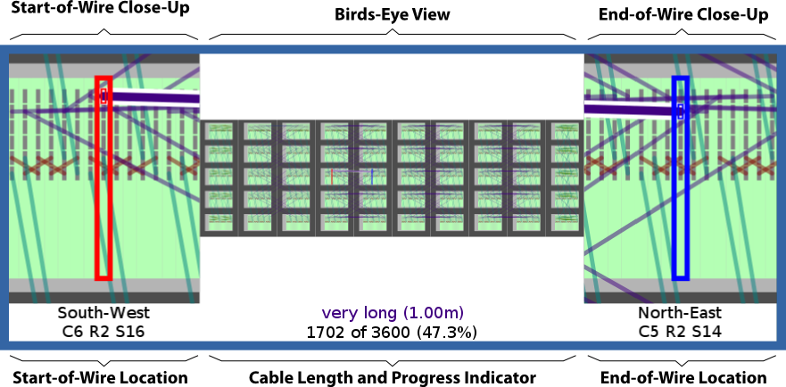
Interactive Wiring Guide
The SpiNNer library has recently been extended with an interactive wiring guide which will give verbal instructions and control LEDs on actual SpiNNaker hardware to guide a technician or easily convinced PhD student through the laborious process of wiring up a large machine. A timelapse video of me wiring up the 103,680 processor SpiNN-105 machine can be seen below:
An annotated screenshot of the wiring software can be seen below with the plan for the 106 machine (10 times larger):
Wiring up SpiNNaker
The circuit boards in a 100,000 processor SpiNNaker system are logically laid out as shown below:
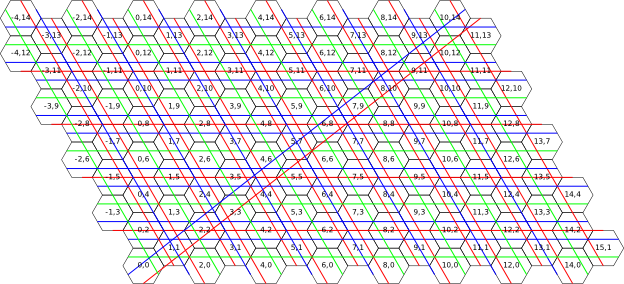
In this configuration, the touching edges of each board (shown here as a hexagon) are connected and long wires stretch from opposing edges. This means that if a piece of data is travelling in a particular direction through the computer when it reaches the edge it simply jumps back around to the other side. The computer is connected up like a 'torus' (or doughnut): imagine walking in a straight line along the surface of a giant doughnut, no matter which way you walk you'll eventually come back to where you started.
Sadly because of SpiNNaker's doughnut shape it means that there are a few very long wires which cross from one side of the system to the other. This is a problem because sending data over long wires is tricky and slow and so it must be avoided to keep the system fast.
After lots of thinking playing around along with others (particularly Steve Furber and Simon Davidson) we realised that if you fold the system in on itself you can bring the maximum length of wire required right down, even for really big systems. The attached wiring guides explain in detail (with more diagrams) how the folding works.
Here is a picture of what is planned to be the largest SpiNNaker machine. It is 10 times larger than the one above with 1,000,000 processors. This time the boards are slotted into racks inside 10 cabinets as they would be when assembled in the real world.
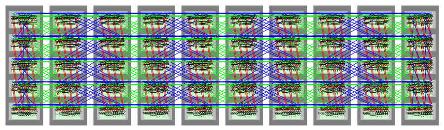
If the machine had been set out as in the first picture it would have required wires of more than 10 meters in length. After using the folding trick mentioned above, the system the longest wire required becomes less than a meter.
Experimenting With Wiring
SpiNNer contains a library designed to allow experimentation with possible board
placement schemes in the ./model/ package. An initial placement like the first
image above (complete with wiring) can be created like so:
torus = board.create_torus(20, 20)This creates a 20-by-20 'threeboard' torus on a hexagonal coordinate system.
Configurations of boards are represented as a list of (board, coordinate) pairs.
The coordinate value in this case is a coordinates.Hexagonal coordinate and
represents the position of its associated board in a Hexagonal space. Various
functions are provided which can map these coordinates to new values to yield
different physical placements of boards.
A each board is an instance of board.Board. Together, the instances of Board
generated by board.create_torus() make up a graph where each Board is a node
in the graph and the edges between them are the wires. Here's an example of
how to navigate the graph:
# Follow the North wire from board
board_to_the_north = board.follow_wire(topology.NORTH)

# Follow the South wire from board_to_the_north and we get back to board
board_again = board.follow_wire(topology.NORTH)
Because the boards are immutable this means that the wiring is never changed and so will not become invalid no matter how the board coordinates are transformed1.
Various interesting transformations are provided to map the boards into new positions and coordinate systems. For example:
# Convert from hexagonal to Cartesian coordinates. The arrangement of boards
# resembles a rhombus.
cart_torus = transforms.hex_to_cartesian(torus)

# Cut the left-hand side of the rhombus off and move it to the right to form a
# rectangle
rect_torus = transforms.rhombus_to_rect(cart_torus)
Here two transformations are performed on the torus. Though the coordinates
associated with them are different, the Board objects remain the same and so
the wiring represented is still the same.
Here is a quick overview of the files/modules in the model package.
./model/transforms.py- Defines transformation functions for lists of (board, coordinate) pairs. These transformations are the work-horse of the package and allow many manipulations of boards in various coordinate systems.
./model/board.py- Contains the
Boardclass: a graph-style model of a board in the system. Also contains functions for creating torus-connected arrangements of boards and iterating over boards, for example by iterating over the sequence of boards visited by a packet travelling through the network. ./model/coordinates.py- Defines a set of named tuples (with some specialised operators) which
represent coordinates in various coordinate systems. Coordinates of these
types are used by the
transformsmodule and their types are checked to help sanity-check your code. ./model/topology.py- Though most functions are not directly useful it also contains the definitions
of the direction constants such as
NORTHused throughout the system. Also provides various utilities which perform the underlying numerical computations carried out by the transformations. ./model/cabinet.py- A datastructure which defines the physical dimensions of boards, racks and cabinets. Used to calculate real-world physical positions of boards to allow wire-lengths to be estimated.
./model/metrics.py- Currently only contains a function which calculates physical wire-lengths between boards.
./model/tests.py- Contains unit tests for many of the basic functions in the model package.
Drawing Board Configurations
In order to help visualise placements generated using the tools in the model
package, a very rudimentary drawing library is provided in
./diagram.py.
This contains a Diagram class with methods for drawing boards using various
coordinate systems and representations. The class generates code for the TikZ
LaTeX package.
For example, this code generates a diagram similar to the one shown at the top of the page (though the coordinate system used for the labels is different).
import diagram

from model import board
from model import transforms
from model import topology

d = diagram.Diagram()

# Create a small system of boards on a hexagonal coordinate system
boards = board.create_torus(8,5)

# Create a dictionary which maps boards to coordinates to use for labelling
# boards in the diagram.
board2coord = dict(boards)

for board, coords in boards:
    # Draw the board on the diagram as a hexagon
    d.add_board_hexagon(board, coords)

    # Label it with its coordinates
    d.add_label(board, r"\tiny %s"%(str(tuple(board2coord[board]))))

    # Draw the wires connecting it to its neighbours in different colours
    d.add_wire(board, topology.NORTH, ["red"])
    d.add_wire(board, topology.EAST, ["green"])
    d.add_wire(board, topology.SOUTH_WEST, ["blue"])

# Output the TikZ code for the diagram
print d.get_tikz()
Extensive use of this class is made in the wiring guide generator in
./wiring_guide.py.
You may find that for large diagrams LaTeX runs out of memory and may need to change your LaTeX configuration to give it more space.
-
Bad coordinates are very definitely possible: there is nothing stopping two boards being given the same coordinate. Though this doesn't make the wiring invalid, it does mean your placement scheme becomes impossible. ↩