A(T)Tiny(85) Piano
My brother recently turned 21 and to mark the occasion it seemed appropriate to send him a birthday card. My first idea was to make him a singing birthday card which plays Morning Mood by Grieg. Since he is training as a teacher, and this particular piece of music haunted us in every assembly we attended in school, it seemed like an appropriate wind-up. As I object to buying cards (albeit with a custom tune programmed in) I set out to make one using one of the aptly-named 8-pin ATtiny85's I had lying around. Unfortunately making small, battery powered electronics is hard so I decided that if it was going to be bulky anyway it might as well feature a fully playable piano keyboard...
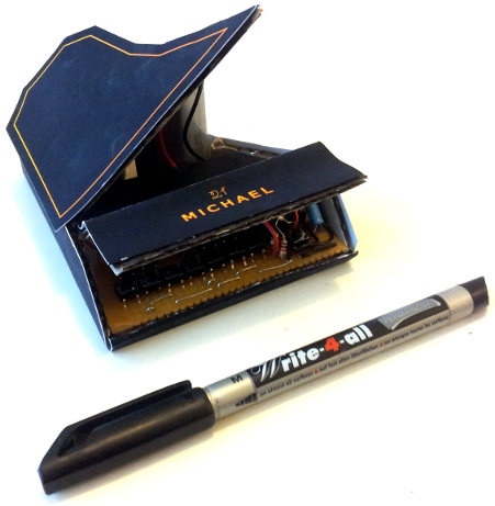
The finished card features:
- "Demo" playback of Grieg's Morning Mood
- 12 (fully chordable) keys
- A configurable arpeggiator to approximate true polyphonic chords
- Key shifting
- Multiple octave support
- A written message inside :)
Construction
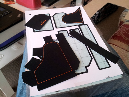
The card's skeleton is made out of an old cardboard box cut into a net and glued together using hot glue.

The skin was printed on some matte-finish printer card and cut out using my handy reverse-engineered Silhouette Portrait cutter/plotter.
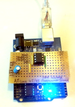
Luckily, the circuit board fit so well it didn't even need gluing in place and so it can be easily removed should it need upgrading (or more likely fixing...)1. The 9V battery also very handily serves as a prop for the lid of the piano!
Electronics
The electronics for the project were kept simple and mostly recycled:
- ATtiny 85
- in an easy-to-solder DIP package. I bought a few of these a while back out of a desire to have a selection of so-cheap-they're-nearly-disposable microcontrollers on hand for projects just like this.
- Tactile Switches
- cheap, clicky and perf-board friendly. Harvested from a discarded circuit board in a lecturers' office, presumably the remains of a printer.
- Lots-o-resistors
- nothing special, scrounged from various sources.
- LF50C
- a low drop out 5V regulator pilfered from university supplies. Though an inefficient way to run off a 9V battery, that isn't a problem for this project.
- 10uF Electrolytic Capacitor
- after a frustrating morning of trying to make the electronics run off the regulator I finally realised that you really do need a capacitor on the output of the regulator...
- Piezo buzzer
- cheap and cheerful (and with no built-in controller).
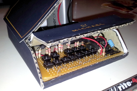
The ATtiny really lives up to its name and unfortunately this comes at the expense of the pin count: a mere 8 pins. Given that two of these would be taken up by power connections and a third by the reset signal2. This left 5 pins through which to connect 13 buttons (12 piano keys and a modifier switch) and a piezo to make the sound.
Traditional approaches to connecting large numbers of switches to only a small number of pins use row/column scanning but this has the limitation that some combinations of key presses can be ambiguous. This is fine for a keypad where only a small number of keys would be pressed at once but since a musical keyboard must support arbitrary chording of keys, an alternative was needed.
The solution I settled on was to make use of the generous 3 analogue inputs provided by the ATtiny. The basic idea is that if each key is given a unique resistance, it should be possible to work out from the total resistance which switches are pressed and which aren't3. The circuit used looks something like this:
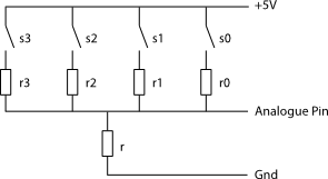
You'll notice that the circuit is set up a potential divider which allows us to measure the resistance of the parallel circuit of resistors with switches at the top. The resistance of the switches and resistors can be calculated as follows:
Stuffing this through the potential divider then yields the following value on the analogue input:
With the number of buttons multiplexed are limited to four and the resistors are chosen as roughly powers-of-two, the range of values for all possible key-presses is kept reasonably far apart meaning that it is easy to distinguish between all possible key combinations. With three analogue inputs and twelve keys, this works out ideally leaving two pins for the mode button and piezo.
Software
The code is available on GitHub if you really wish to take a peek.
As mentioned, the show is run by a single ATtiny85. Luckily this tiny chip can be programmed via the Arduino IDE or choice of Makefiles which makes using it very pleasant for people who are lazy or lacking in proper microcontroller development skills. Indeed you can even program it using an appropriately programmed regular Arduino meaning I didn't need to buy any fancy hardware.
The down-side is that unlike the regular Arduino, some library functions are
somewhat poorly supported. In particular the tone(), noTone() functions
which I was hoping to use to generate the required sounds didn't work. Though
others claim to have fixed this
issue, the implementation didn't
generate the correct frequencies. As a result I simply implemented them by hand
using the ATtiny's internal
timer/counter.
Given that I was lazy, I ended up doing this using an interrupt (starting from
some semi-functioning examples found online) rather than doing it properly using
the PWM generator.
The other issue is that working on a tiny 8-bit microcontroller doesn't lend
itself to doing floating point calculations for working out the analogue input
values for all the possible button presses. As a result I wrote a small python
script
which, given a set of resistor values, produces an #include-able code
snippet
with the analogue values pre-computed in a look-up table.
Conclusions
Luckily, my brother was absolutely delighted and amused by the card, despite the iffy paper-craft, electronics, soldering and software... :)
This is also the first project I've done using an ATTiny and while I was largely pleased with how Arduino-ey it was, it definitely required substantially more effort than its dev-board dwelling cousin. Having said that, much fun was had and I'm very pleased with how well the analogue key multiplexing.
-
What do you mean you've never upgraded your birthday card's firmware before?! ↩
-
It is possible to configure the ATtIny's fuses to allow the reset signal to be used for GPIO but I didn't use this feature in the end. ↩
-
This is essentially how digital-to-analogue converters work so this isn't a new idea. ↩