The Tickysim SpiNNaker Model
Tickysim is a timing-based simulator of the inter-chip interconnection network of the SpiNNaker architecture. This article describes the configurations used by on-going work comparing the simulator with a Bluespec SystemVerilog simulator implemented on an FPGA and the actual SpiNNaker hardware.
Simulator
The Tickysim simulator is written in C and implements a synchronous model of SpiNNaker's asynchronous interconnection network. A clock tick in the simulator is defined to correspond with a clock tick in a SpiNNaker router. All other timing parameters in the model are calculated in terms of this definition.
Tickysim's model consists of a set of components, such as arbiters, routers and packet generators which communicate exclusively via fixed-length FIFO buffers. At each clock tick, every component executes a 'read' phase followed by a write phase. For example, an arbiter may check for waiting packets in its input buffers and space in its output buffer during the read phase and then, during the write phase, extract a packet from the selected input buffer and place it in the output buffer. All read phases must complete before any write phases begin which ensures that the simulator's behaviour does not depend on the order components execute.
Network
At the highest level of abstraction, the model consists of a network of 'nodes', which represent individual SpiNNaker chips, connected via models of the slow chip-to-chip links. The network's topologies and link model are described below.
Topologies
The following two network topologies were used in experiments. In each topology, the model of a link remains the same.
The first is a 12x12 hexagonal torus topology shown below. In this topology nodes are connected to their (six) immediate neighbours and nodes at the edge of the network wrap-around to those on the other side of the network (not shown in the figure for clarity). All links are modeled as being identical. This topology mimics the (logical) topology of a three board SpiNNaker configuration.

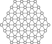
The second topology consists of a set of a hexagonal segment of a hexagonal mesh of nodes shown in the figure below. Nodes are connected to their six neighbours except around the edges of the network where only a subset of the links are connected. Once again, all links are identical. This topology mimics that used by a single 48-node SpiNNaker board.
Link Model
In SpiNNaker, chips are connected via asynchronous 2-of-7 links which are modelled by a delay element. Once a packet becomes available in its input buffer and its output buffer has a space, the packet is forwarded by the delay element after a fixed delay of 16 cycles. This value is derived as follows: A SpiNNaker link nominally runs at 250 Mb/s1 which equates to one 40 bit packet every 160 ns. Since the SpiNNaker router runs at 100 MHz this equates to one packet every 16 router cycles, hence the 16 cycle delay in the model.
Node Model
Each node in the simulation corresponds to a single SpiNNaker chip and is illustrated below. The nodes contain a router, packet generator, packet consumer and a tree of two-input round-robin arbiters which arbitrates between the inputs to the router.

Router
The router consists of a 4-stage pipeline. Each cycle, the router attempts to route the packet at the end of the pipeline to the appropriate output. It will also attempt to accept a packet from the input buffer each cycle. Packets are routed using dimension-order routing through the system. The SpiNNaker 'emergency routing' scheme is not used. If a packet cannot be forwarded to its requested output after 50 cycles at the head of the router, it is dropped.
Packet Generator
The packet generator generates packets destined for each node of the system in turn starting with the node to the East and proceeding from left-to-right and top-to-bottom, skipping itself. When a packet is generated, the packet generator waits for a specified period before attempting to generate another packet. If its output buffer is full, the packet generator waits until a space becomes available and then sends the packet immediately.
The wait period of the packet generator controls the packet injection rate into the network. Appropriate delays can be calculated in a similar fashion to the link delay described previously.
Packet Consumer
The packet consumer attempts to receive any incoming packets immediately. Once a packet has been accepted, however, the packet consumer will wait 10 cycles before accepting another packet.
Arbiter Tree
The structure of the arbiter tree is based on that used in SpiNNaker's NoC.
The asynchronous arbiters in SpiNNaker are modelled instead with synchronous round-robin arbiters. The input arbiters consist of two-input round-robin arbiters. Each cycle, an arbiter selects a waiting packet on one of its inputs and forwards it to its output if there is space in the output buffer.
Buffers
The buffers at the inputs of the arbiter tree contain two slots. The buffer between the output of the tree and the router also contains two slots.
SpiNNaker features 'bandwidth aggregators' between levels of the arbiter tree. These asynchronous devices read in a single packet on a narrow input bus and then forward it on a wider (and thus higher-bandwidth) output bus. As such, these devices act like a single slot buffer and hence are modelled as such in the arbiter tree.
The buffers at the outputs of the router contain two slots.
Experimental Procedure
During simulations, the simulator is first allowed to warm up for 100,000,000 cycles during which time the system's state is not recorded. After the warm up period the simulators runs for a further 10,000,000 cycles during which time various metrics are recorded. The simulator is completely restarted before each experiment. The most notable (raw) measurements recorded by the simulator are:
- Number of Packets Sent
- A total count of the number of packets successfully injected into the network by the packet generators.
- Number of Packets Arrived
- The total number of packets which arrived at the packet consumers.
- Number of Packets Dropped
- The total number of packets which were dropped due to the router timing them out.
- Warm up duration
- Wall-clock duration of the warm up phase.
- Sample duration
- Wall-clock duration of the time spent during the non-warm up phase of the simulation.
From these raw measurements, the following additional metrics can be derived:
- Network Accepted Load
- The amount of traffic accepted by the network. Calculated as
$\frac{\textrm{packets arrived}}{\textrm{injection rate} \times \textrm{simulation duration}}$ . - Network Packet Drop Rate
- The number of packets dropped as a proportion of those successfully injected
$\frac{\textrm{packets dropped}}{\textrm{packets injected}}$ .
Simulator Execution Environment
Simulations were run out of hours on idle computers in the undergraduate laboratories. The machines are based on Intel Core i5-2400 Processors running at 3.10 GHz and 8 GB of RAM.
Though the simulator has not been parallelised, individual instances of the simulator testing specific injection rates/topologies were run simultaneously across multiple machines using GNU Parallel.
-
The SpiNNaker chip-to-chip links do not run at a uniform rate of 250 Mb/s as they rely on asynchronous communications. As a result, differences in circuit board and chip layout/manufacturing can cause variations in performance between different chips and different links. ↩